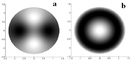
Fig.1. Response function of one of the middle ring electrodes. (a) calculated; (b) experimentally measured.
Formation of the given laser beam intensity and phase is an important practical and scientific problem. Bimorph flexible mirror is one of the most widely used devices for this purpose. We present a new approach of multilayer bimorph mirrors and a numerical model to simulate them, based on the finite elements method. The multilayer mirror consists of a substrate and a number of PZT layers.
Keywords: bimorph corrector, laser beam control, aberrations.
In modern laser technologies, in particular in nano technologies, it is often necessary to form and control a specific intensity distribution on the surface being treated. One of the simplest ways to achieve the best beam focusability and profile control is to use the systems of adaptive optics. Such systems consist of the wavefront corrector, sensor and some electronics to control of the corrector’s surface. Main element of any adaptive system is the corrector which determines the properties and ability of the system.
It is very well known that conventional bimorph corrector (or mirror) is intended to reproduce and thus correct for low order aberrations of the wavefront [1]. Traditional bimorph mirrors have the diameter of more than 30 cm, but a large number of industrial and scientific applications need a noticeably smaller diameter. The use of beam expanders (reducers) is not the perfect way to fit small beams to large aperture mirror.
We developed the new type of corrector – a small aperture (tiny) deformable multilayer mirror. Such mirrors could be easily integrated into flexible programmable machines or laser robots and they allow optical systems to be more compact and reliable.
A conventional semipassive bimorph mirror consists of passive substrate made of glass, silicon or copper and active piezoceramics (PZT) disk firmly glued to substrate. There is a grid of electrodes placed on the outer surface of PZT disk to reproduce the main aberrations. When we apply voltage to control electrodes, transverse piezoelectrical effect induces stress in PZT and the mirror bends. In this paper we will consider circular mirrors with segment-shaped control electrodes.
One of the most important characteristics of the bimorph mirror is a set of the response functions of its electrodes. Some models of the bimorph mirror have already been studied, but as we have shown previously [2] it is more practical to use numerical methods, in particular, variation approach of the finite element method.
This approach is a very powerful and effective method for treating thin plate bending. The multilayer plate is assumed as a unity of a large number of finite elements of simple form (triangular in our simulations). Actually these elements are prisms with the thickness that equal to the mirror in the element location. But the thin plate approach deals with flat elements. The properties of each of these simplified elements are determined by the properties of the corresponding prism element. Different parameters of the layers constituting the prism, including presence and absence of PZT are taken into account. Thus here is the way to consider different radii of PZT and substrate layers and difference in their Poisson coefficients. The next step is to simplify all volume forces (caused by neighborhood elements and piezoelectric tension) acting upon the element to the system of nine nodal forces and nodal moments. The elements are, by assumption, parts of the thin plate, so one can easily derive the relation between extended nodal forces (forces and moments) and element deformation. Each element deformation can be determined by nine extended nodal displacements (displacement itself and two orthogonal tilts, every in each of the three nodes) by treating it as a sum of 9 polynomials of the third order. Assuming the Huke (linear) law of mirror deformation the relation between extended nodal forces and displacements can be brought to the form of linear system of nine equations. The equation of mirror equilibrium states that forces in each node should be balanced, thus one acquires a system of linear equations with extended nodal displacements as unknowns, extended nodal forces as a right side column and elements of the square matrix determined by each element configuration. Each element interacts only with a few neighborhood elements, so the matrix of the system is sparse. Boundary conditions are determined by the type of mirror clamping and give a number of additional equations for extended displacements in boundary nodes, which override that, derived from mirror equilibrium condition. As the mirror type that we consider usually has almost free clamping to increase peak-to-valley deformation, we simply leave equations, which state equilibrium in boundary nodes. All this stuff has been embodied in the MATLAB program.
Calculated mirror deformation well corresponds to experimentally measured one. It is demonstrated in Fig. 1, which shows: a – calculated response function profile, b – measured one. Electrode location is shown in Fig.1a with solid line. Relative root-mean square deviation of these profiles is 6%. This value fits common accuracy of measurement with Shack-Hartmann wavefront sensor, thus proving quality of our bimorph mirror modeling.
A laser beam often has significant number of low order aberrations, and mirror should have large stroke while reproducing them. Simultaneously, there are higher order aberrations, that have smaller amplitude, but quality of their reproducing is more crucial. It is very difficult to achieve simultaneously good quality and large amplitude with the use of only one PZT layer. The first step to solve this problem is the use of additional PZT layer with one large electrode, which occupies the whole PZT surface. Its response function is parabolic and this electrode is often stated as focus/defocus electrode. Light modifications of our software for mirror modeling allow treating of such mirrors: we only have to add piezoelectric forces coming from the second PZT disk.
While trying to determine electrode spacing one have faced a problem: different aberrations require different electrode spacing (it is obvious), and moreover different radii and angles of sectioning to be reproduced. That is why the number of electrodes increases rapidly, though every aberration itself requires a small number of electrodes. The idea is the following: let us use the second layer (reproducing only defocus) to reproduce one more aberration, say astigmatism. The outer layer is to reproduce, for example, spherical aberration. This mirror has been manufactured and is one of our first examples of the tiny bimorph mirrors (Fig. 2). The mirror parameters are following: substrate thickness 1.5 mm, its diameter: 20 mm, each PZT layer thickness: 0.35 mm, PZT radius: 15 mm, the mirror has two PZT layers, the control electrode grid (outer surface) and another electrode grid are shown in Fig.2a. If we simultaneously apply the same voltage to all electrodes of the outer layer from Fig.2a, then it would act as a defocus electrode. If we apply voltage of equal absolute value, but of the different signs to the electrodes of the inner PZT layer, we will reproduce astigmatism. The electrode grid on the outer PZT layer, presented in Fig.2a, is common for reproducing spherical aberration. Radius sectioning is 0.38 and 0.73 times PZT radius.
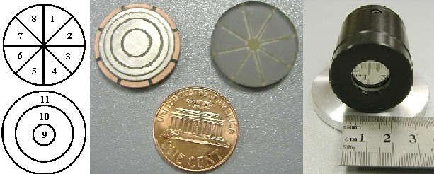
Simulated mirror astigmatic surface is presented in Fig.3a. The good fact about the simulations is that maximum of mirror deformation is not near the mirror edge, but 4.4 millimeters from it. It is very good in applications because usually the real beam illuminates central part of the mirror, which is 3 or 4 millimeters smaller, than mirror diameter. Let us consider the outer layer. Electrode sectioning radii are 2.9 millimeters and 5.5 millimeters. Mirror deformation when reproducing spherical aberration is shown in Fig.3b. The difference between experimental surface of the mirror and ideal spherical aberration derived numerically is 15%.
The most advanced mirrors have 2 layers of PZT with the electrode grid, designed to reproduce low order aberrations. Let us add one (and later even more) active layer. Negative effect is the increase of mirror thickness: it greatly reduces mirror sensitivity. The previously considered mirror could reproduce only three aberrations, but coma is also very common in optical systems. Adding a new layer allows us to use electrode grid for this aberration.
One of the most important parameters, which determines PZT layer sensitivity is its distance from median plane. Median plane is a surface where material deformations are absent, when the plate itself bends. If median plane is situated in the middle of PZT layer, then applying voltage to this layer doesn't cause any mirror deformation.
We have numerically investigated a new generation of the bimorph mirrors and showed how their design follows the previous development of the bimorph mirrors. The results are very promising, we can use mirrors with a multiple number of active layers to independently compensate for different aberrations. As we have shown, small variation in mirror thickness can significantly influence the mirror performance.
For more technical information please visit Tiny mirrors page.